
Nitrogen blanketing pressure gauge selection is a low-pressure tank instrumentation task, not a simple catalog choice. The gauge may read only a few mbar or kPa above atmosphere, yet the reading affects product oxidation control, regulator troubleshooting, conservation vent behavior and operator safety around inert gas. This guide explains how to specify the pressure range, sensing element, mounting point and RFQ data while keeping tank venting and oxygen-deficiency hazards in the engineering review.
What nitrogen blanketing pressure gauge selection means
Nitrogen blanketing pressure gauge selection starts with the purpose of the blanketing system. Nitrogen blanketing, also called tank inerting, adds inert gas to the vapor space of a storage tank so oxygen ingress, moisture pickup and flammable vapor formation are reduced. The gauge is a local indication of vapor-space pressure; it is not the blanketing valve, the conservation vent, the flame arrester or the oxygen safety system.
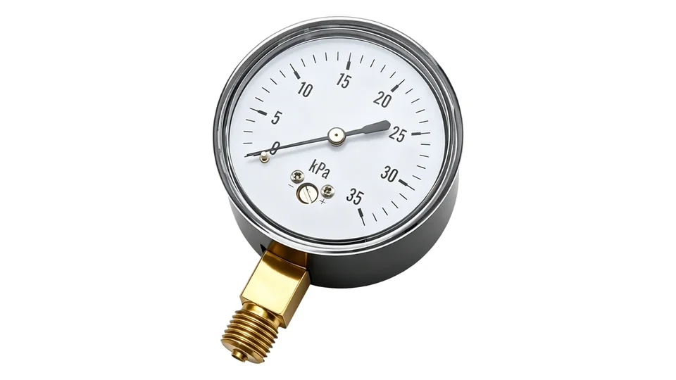
Because many blanketed tanks operate close to atmospheric pressure, the instrument may need to show mbar, inH2O, mmH2O or kPa with enough resolution for operators to see small changes. A normal industrial Bourdon tube gauge may be too coarse for this duty. Low-pressure capsule or diaphragm gauges are often reviewed when the range is in the 0-60 kPa class or lower.
Use the gauge to help answer practical questions: is the tank holding slight positive pressure, is the regulator feeding nitrogen, is the vent lifting, is there unexpected vacuum during pump-out, and is maintenance seeing a stable local indication?
Compare Low Pressure Gauge OptionsReview capsule, diaphragm and connection choices→Define the low-pressure range before choosing the gauge
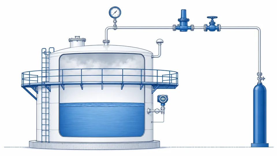
Do not start from the nitrogen supply cylinder pressure or plant nitrogen header pressure. The gauge installed on the tank or blanketing line should match the controlled tank pressure, vent setting, possible vacuum exposure and any hydrostatic or cleaning condition that can reach the gauge connection.
| RFQ input | What to state | Selection effect |
|---|---|---|
| Normal blanketing pressure | Expected mbar, inH2O, mmH2O or kPa range in the vapor space | Determines whether a capsule, diaphragm or other low-pressure element is needed. |
| Vent and vacuum settings | Pressure-vacuum vent opening points and emergency venting philosophy | Prevents treating the gauge as a tank protection device. |
| Nitrogen supply condition | Regulated pressure after blanketing valve, not only cylinder pressure | Separates supply-side troubleshooting from tank pressure indication. |
| Process movement | Filling, pump-out, thermal breathing, cleaning and transfer rate | Explains why the reading changes during operation. |
| Medium exposure | Vapor, solvent, condensate, corrosive fumes or sticky product | Controls wetted material, seal and clogging review. |
API Standard 2000 is commonly referenced for atmospheric and low-pressure storage tank venting. It covers normal and emergency venting causes such as liquid movement, thermal effects and operational upsets; a local gauge can support observation, but vent sizing and tank protection remain an engineered design responsibility. For a public copy of an older edition, see API 2000: Venting Atmospheric and Low-Pressure Storage Tanks.
Size the range around the tank's pressure band, not around the nitrogen header
A blanketing system works inside a narrow band of pressures, and every setpoint in that band belongs to a different device. From the bottom of the band upward: the blanketing regulator opens when tank pressure falls to its setpoint; the tank normally sits a little above it; the backpressure or vent regulator opens when pressure rises; and the pressure/vacuum relief valve is the last mechanical protection before the tank structure itself is at risk. The local gauge has to resolve the differences between those settings. That is why the supply pressure of the nitrogen header, which may be several bar, is irrelevant to the range choice.
| Device in the band | Position relative to the others | What the local gauge has to make visible |
|---|---|---|
| Blanketing (make-up) regulator | Lowest setpoint in the band | Whether the tank is riding on the regulator or has fallen below it |
| Normal operating pressure | Just above the make-up setpoint | The steady-state value, ideally near the middle of the dial |
| Backpressure or vent regulator | Above normal operating pressure | Whether the tank is venting, and therefore wasting nitrogen |
| Pressure/vacuum relief valve | Highest positive setpoint, below tank design pressure | How much margin remains before the last mechanical protection lifts |
| Vacuum side | Below atmospheric, during out-breathing or cooling | In-breathing conditions a positive-only range cannot show |
API 2000 covers venting requirements for atmospheric and low-pressure storage tanks and is the usual reference for sizing normal and emergency venting. It governs the venting devices, not the indicating instrument, so the gauge range still has to be derived from the setpoints the tank vendor supplies together with the tank's design pressure and design vacuum. Reading a gauge range out of a venting standard is a common specification error.
The practical consequence is a range decision that looks unusual to anyone used to process pressure gauges. On a fixed-roof tank whose control band sits between roughly 5 and 25 mbar, a 0-40 mbar or 0-60 mbar capsule gauge places the normal value in a readable part of the scale, whereas a 0-1 bar Bourdon gauge would compress the entire control band into the first few degrees of pointer travel and make the difference between blanketing and venting invisible. Units are worth confirming in writing as well, because mbar, mm H2O and inches of water column all appear in tank documentation, and a mismatch between the datasheet and the dial is a routine cause of rework.
Confirm the vacuum side before the order is placed. Tanks are emptied as well as filled, and a compound capsule range such as -10/+40 mbar shows the in-breathing condition that a positive-only range hides entirely. The arithmetic behind placing an operating point sensibly on a scale is set out in pressure gauge range calculation, and the relationship between an indicating gauge and the relief devices around it is covered in pressure relief valve gauge selection.
Capsule, diaphragm or Bourdon tube for nitrogen blanketing pressure gauge selection
For slight positive pressure, the sensing element matters. A Bourdon tube is robust for many industrial pressure ranges, but it may not give useful resolution at very low tank blanketing pressures. A capsule element uses two corrugated diaphragm halves and is intended for low-pressure indication. A diaphragm gauge can also be used for low ranges, especially when the vapor or condensate may be less clean.
Manogauge product data lists capsule pressure gauge options with a 0-60 kPa range, Ø60-150 mm dial size, SS / brass material choices, ±1.6 / 2.5% accuracy classes and G/PT/NPT 1/4 connections. For dirty or corrosive vapor paths, compare diaphragm pressure gauge options and confirm wetted materials with the stored product.
The product range is a starting point only. Solvent vapor, food oil, resin monomer, wet nitrogen, acid fumes or explosive-area requirements can change the final instrument specification. Do not assume compatibility from low pressure alone.
Send Tank Blanketing DataInclude pressure unit, vent settings, vapor and mounting point→Install the gauge where the reading has diagnostic value
A tank blanketing system can have several pressure points: plant nitrogen header, regulator inlet, regulator outlet, tank vapor space, conservation vent line and emergency vent area. A supply-side gauge can show whether nitrogen is available, while a vapor-space gauge shows whether the tank is actually holding the intended slight pressure. These readings answer different questions.
Install the vapor-space gauge where condensate cannot fill the socket and where operators can read it without standing in a possible inert-gas release path. Use an isolation valve only when site procedure prevents accidental closure from hiding a dangerous condition. If maintenance needs remote reading or alarms, a pressure transmitter may be required in addition to a local dial gauge.
For thread and sealing basics, review the pressure gauge thread connection guide. If the line can see pulsation, sudden pressure spikes or vacuum, compare the pressure gauge overpressure protection guide before selecting accessories.
What a nitrogen blanketing pressure gauge cannot prove
A gauge cannot prove that oxygen concentration is safe, that the tank is correctly inerted, that the vent is sized, that the flame arrester is clean, or that a confined-space atmosphere is breathable. Nitrogen is colorless and odorless, and it can displace oxygen without warning. The U.S. Chemical Safety Board has documented fatal nitrogen asphyxiation incidents and stresses that inert gas can make process equipment and nearby breathing zones hazardous; see the CSB Hazards of Nitrogen Asphyxiation safety video page.
For this reason, oxygen monitoring, ventilation, entry permits, lockout practices and confined-space procedures must be handled separately from gauge selection. OSHA guidance also treats oxygen-deficient atmospheres as a recognized hazard; the gauge reading is not a substitute for atmospheric testing.
A stable blanketing pressure also cannot prove product quality. Oxidation control, moisture control, vapor emissions and flammability risk depend on tank design, gas purity, venting, operating sequence and process chemistry. The final design should be approved by the responsible process, safety or tank engineer.
RFQ checklist for nitrogen blanketing pressure gauge selection
A useful RFQ for nitrogen blanketing pressure gauge selection should include the stored product, tank type, normal blanketing pressure, vent and vacuum settings, possible vacuum exposure, nitrogen supply pressure after regulation, vapor temperature, condensate risk, hazardous-area requirement, dial size, accuracy need, connection thread, mounting position, wetted material and certificate requirements.
- State whether the gauge is on the tank vapor space, regulator outlet, nitrogen header or vent line.
- Provide the pressure unit expected by operators: mbar, inH2O, mmH2O, kPa, psi or dual scale.
- Confirm whether vapors are dry, wet, solvent-rich, corrosive, sticky, food-contact or oxygen-sensitive.
- Specify whether the instrument is for local observation only or part of an alarmed monitoring loop.
- Keep tank venting, hazardous-area classification and confined-space safety under the site engineer’s review.
Manogauge, based in Zhejiang, China, supplies low-pressure capsule gauges, diaphragm gauges and stainless steel pressure gauge options for OEM and export projects. Good nitrogen blanketing pressure gauge selection keeps the local indication readable while making its limits explicit.
Key takeaways
- Nitrogen blanketing pressure is usually a low-pressure vapor-space indication, not a supply-cylinder pressure reading.
- Capsule or diaphragm gauges are often more readable than high-range Bourdon gauges for mbar or kPa tank service.
- A gauge supports troubleshooting but does not prove vent sizing, inerting quality or breathable atmosphere.
- RFQs should include tank pressure, vent settings, vapor chemistry, mounting point, materials and safety constraints.
Related buyer pages
Stainless steel pressure gauge manufacturerLow-range stainless gauges for tank blanketing and pad/depad control points.
Diaphragm pressure gauge manufacturerDiaphragm seals where solvent vapour or product carryover can reach the gauge.
Explosion-proof pressure gauge manufacturerSolvent tank farms are often classified areas; confirm zone, gas group and T-class before ordering.
Related reading
- 316L vs Brass Pressure Gauge Wetted Parts: Corrosion Guide
316L vs brass pressure gauge wetted parts compared for corrosion risk in water, steam, ammonia, seawater, chlorides, CIP/SIP cleaning and diaphragm seals.
- A2L R-454B Refrigerant Pressure Gauge Selection
A2L R-454B refrigerant pressure gauge selection for HVAC service: manifold gauge use, PT chart checks, service ports, gauge range and safe workflow.
- Ammonia Refrigeration Pressure Gauge: R717 Materials and Safety
Ammonia refrigeration pressure gauge guide for R717 cold storage: suction, discharge, oil, defrost ranges, material compatibility and safety checks.
- Oxygen Pressure Gauge Selection Guide
Oxygen pressure gauge selection guide for clean service: oil-free handling, materials, range, dry case choice, packaging, installation and RFQ checks.
- Dry vs Liquid-Filled Pressure Gauges: Fill and Vibration Guide
Dry vs liquid-filled pressure gauge guide comparing glycerin, silicone oil and dry case designs for vibration, pulsation, temperature and maintenance risk.
Frequently asked questions
What range is typical for a nitrogen blanketing pressure gauge?
Many tank blanketing applications are specified in mbar, inH2O, mmH2O or low kPa rather than high psi or MPa. The exact range must follow the tank design pressure, blanketing valve setting and pressure-vacuum vent settings.
Is a capsule gauge better than a Bourdon tube gauge for tank blanketing?
Often yes for very low pressure because a capsule element gives more usable pointer movement at small pressure changes. A Bourdon tube may still be suitable on higher-pressure supply or regulator points.
Can a tank pressure gauge replace oxygen monitoring?
No. Nitrogen can displace oxygen without odor or color. A pressure gauge only shows local pressure; it does not measure oxygen concentration or prove that the atmosphere is safe to breathe.
Where should the nitrogen blanketing gauge be installed?
Install it at the point you need to diagnose: vapor space for actual tank pressure, regulator outlet for blanketing valve behavior, or supply header for nitrogen availability. Avoid condensate traps and unsafe reading positions.
What should be included in an RFQ for a blanketing gauge?
Include tank type, stored product, normal pressure, vent and vacuum settings, nitrogen pressure after regulation, vapor temperature, condensate or corrosion risk, hazardous-area requirement, dial size, accuracy, thread, materials and certificates.
Why not use a 0-1 bar gauge on a blanketed tank?
Because the entire control band would occupy the first few degrees of pointer travel. A typical fixed-roof tank operates between roughly 5 and 25 mbar, which is 0.5 to 2.5 percent of a 0-1 bar span. At that position the operator cannot distinguish a tank riding on the make-up regulator from a tank venting through the backpressure regulator. A 0-40 or 0-60 mbar capsule element puts the same band across most of the dial.
Does a blanketing gauge need to show vacuum?
Usually yes. Emptying the tank or cooling the vapour space produces in-breathing, and a positive-only range simply parks the pointer on the stop while it happens. A compound capsule range such as -10/+40 mbar makes the vacuum excursion visible, which matters because tank vacuum damage is generally more common and more expensive than overpressure damage on atmospheric and low-pressure tanks.