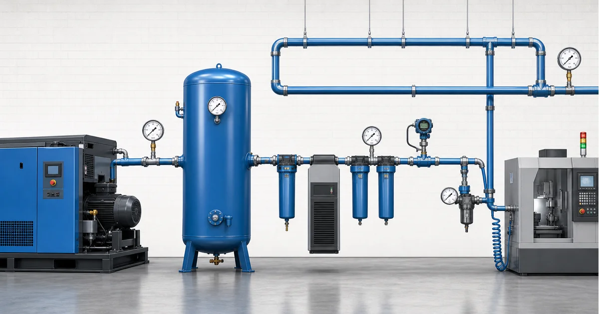
Compressed air pressure gauge selection means choosing local gauges, differential readings or transmitters for an air system that includes the compressor package, receiver, dryer, filters, distribution piping and point-of-use regulators. The goal is not simply to show compressor discharge pressure. Good gauge placement helps maintenance teams find pressure drop, filter loading, regulator drift, leaks and unsuitable point-of-use pressure before production equipment loses force or speed.
What compressed air pressure gauge selection should prove
Compressed air pressure gauge selection should prove whether each part of the air system has enough pressure for its actual function. A compressor discharge gauge proves what the package can produce. A receiver gauge shows stored pressure. Gauges before and after dryers or filters show whether pressure drop is normal or rising. A regulator gauge confirms the pressure delivered to pneumatic tools, valves, cylinders or packaging machines.
The Compressed Air and Gas Institute defines pressure drop as loss of pressure in a compressed air system or component due to friction or restriction. The U.S. Department of Energy sourcebook also treats leaks and unnecessary system pressure as energy problems; lower pressure reduces leakage through an opening. See the CAGI resource library and the DOE compressed air sourcebook for background.
The main keyword for this article is compressed air pressure gauge selection. Related terms include compressed air pressure drop, pneumatic system pressure gauge, filter differential pressure gauge and point-of-use air pressure monitoring.
Review Stainless Steel Gauge OptionsExplore 143+ industrial gauge models→Pressure points from compressor room to point of use
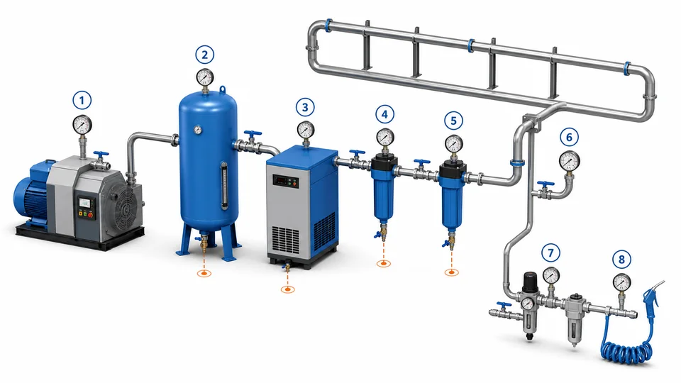
Use more than one reading when diagnosing a compressed air complaint. A low pressure report at a machine can be caused by compressor control, wet receiver pressure, dryer pressure drop, dirty filters, undersized pipe, closed valves, leaks, regulator setting or a clogged tool hose. One gauge cannot separate these causes.
| Location | What the reading checks | Gauge implication |
|---|---|---|
| Compressor discharge | Package control pressure and load/unload behavior | Range above normal control band, vibration awareness |
| Receiver outlet | Stored plant air before treatment or distribution | Easy-to-read local gauge, isolation valve |
| Dryer and filters | Pressure drop and element loading | Two gauges or differential indicator across the same component |
| Ring main / far header | Distribution pressure under production demand | Durable gauge or transmitter for trend logging |
| Point-of-use regulator | Actual pressure delivered to tools or cylinders | Small local gauge matched to regulator outlet range |
When gauge readings are compared, record compressor state, flow demand, dryer status and downstream valves. A pressure map created during clean, stable operation becomes the baseline for future maintenance.
Budget the pressure drop first, then bracket each item with a reading
Every component between the compressor and the tool consumes pressure, and the only way to see where it goes is to bracket each component with a reading. A practical approach is to write a drop budget before the gauges are ordered: an allowance across the aftercooler and separator, an allowance across the dryer, an allowance per filter stage, an allowance for the distribution main, and whatever remains at the point of use. Once the budget exists on paper, a pair of gauges either confirms it or identifies the item that has drifted.
| Measurement point | Allowance commonly used in system design | What a larger drop usually indicates |
|---|---|---|
| Aftercooler and moisture separator | About 0.1-0.2 bar | Fouled cooler surfaces, high cooling water or ambient temperature |
| Refrigeration or desiccant dryer | About 0.2-0.3 bar | Element loading, undersized dryer for the actual flow, purge or valve fault |
| Each filter stage | Around 0.1 bar clean; change element at the value on the filter data sheet, often 0.3-0.6 bar | Element saturation, oil carryover from the compressor, wrong filtration grade for the duty |
| Distribution main, header to far end | Frequently held below 0.1-0.2 bar by pipe sizing | Undersized pipe, a partly closed isolation valve, leaks, or a ring main broken into a dead end |
| Hose, quick coupling and FRL at the tool | Varies widely and is often the single largest loss | Undersized coupling, long or small-bore hose, regulator set too low for the tool's air demand |
The figures above are planning allowances used in system design, not standard requirements. It is worth being explicit about that, because compressed air carries a standard that is often quoted in the wrong place: ISO 8573-1 classifies compressed air purity for particles, water and oil. It does not set a pressure drop limit, a distribution pressure or a gauge accuracy class. Those come from the equipment data sheets and from the plant's own energy targets.
The commercial argument for measuring is straightforward. Raising compressor discharge pressure to compensate for a restriction nobody has located costs energy continuously, and a widely used rule of thumb puts the penalty at roughly 6 to 7 percent additional compressor power for each extra bar of discharge pressure. That figure moves with machine type and control mode, so treat it as an order of magnitude for a business case rather than a guaranteed saving, and confirm it against the compressor manufacturer's data for the specific unit.
For the drop itself, a dedicated differential gauge is easier to act on than two separate readings subtracted by hand, and it removes the accumulated error of two instruments; the trade-offs are set out in the differential pressure gauge guide for filters. Where a reading only needs to confirm that the system is inside a band, a class 2.5 gauge with the normal value near mid scale is adequate, and accuracy class selection shows where paying for a tighter class is and is not worthwhile.
Range, accuracy and construction for compressed air pressure gauges
Most factory compressed air systems operate in bar or psi ranges far below hydraulic systems, but the gauge must still match maximum allowable pressure, regulator outlet pressure and expected pulsation. A gauge whose normal reading sits near the middle of the dial is easier to read than one operating near zero or full scale. For regulator outlets, a narrow range may improve readability; for receiver or compressor discharge points, overpressure margin matters more.
Accuracy should match the decision. A general maintenance gauge may be sufficient for visual checks, while troubleshooting pressure drop across a filter or validating a regulator setting may need tighter accuracy or a calibrated digital gauge. Dial size should match viewing distance: Ø40 mm may fit a compact regulator, while Ø63-100 mm is easier for compressor rooms and headers.
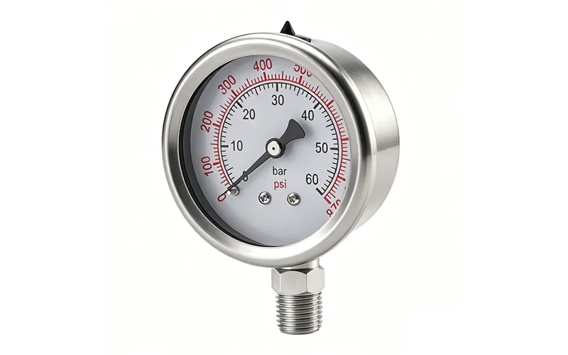
Manogauge product data lists the ZX-01-R stainless steel pressure gauge with 0-100 MPa range options, Ø40-100 mm dial sizes, 304 / 316L stainless steel material options, ±1.0 / 1.6% accuracy and G/PT/NPT 1/2 connection options. For pneumatic equipment with stronger vibration, compare the shock-resistant pressure gauge line before ordering.
The arithmetic behind these percentages, the standard range series and three worked examples are set out in how to calculate pressure gauge range.
Prepare a Compressed Air Gauge RFQOur engineers respond within 24 hours→Material, moisture and installation details
Compressed air is not always clean dry air. Condensate, compressor oil carryover, cleaning chemicals, outdoor humidity and aluminum or steel pipe debris can affect gauge service life. Brass or stainless wetted parts may both appear in pneumatic systems, but the final choice should follow air quality, condensate chemistry, plant standards and surrounding washdown or corrosion risk.
Install gauges with an isolation valve where maintenance is expected. Avoid locations where the gauge blocks a walkway, creates a snag point, or traps condensate in a way that freezes. Thread type must be specified clearly; NPT, BSP, G and metric threads are not interchangeable. For sealing risk, see the pressure gauge thread connection guide. For pulsation at compressors or fast cycling valves, review snubber and pulsation protection.
Do not assume a glycerin-filled gauge is always best. Filling can stabilize pointer movement, but it also changes temperature behavior and service assumptions. Oxygen-enriched, special gas or oil-free cleanroom air systems need separate cleanliness review.
What pressure readings cannot prove
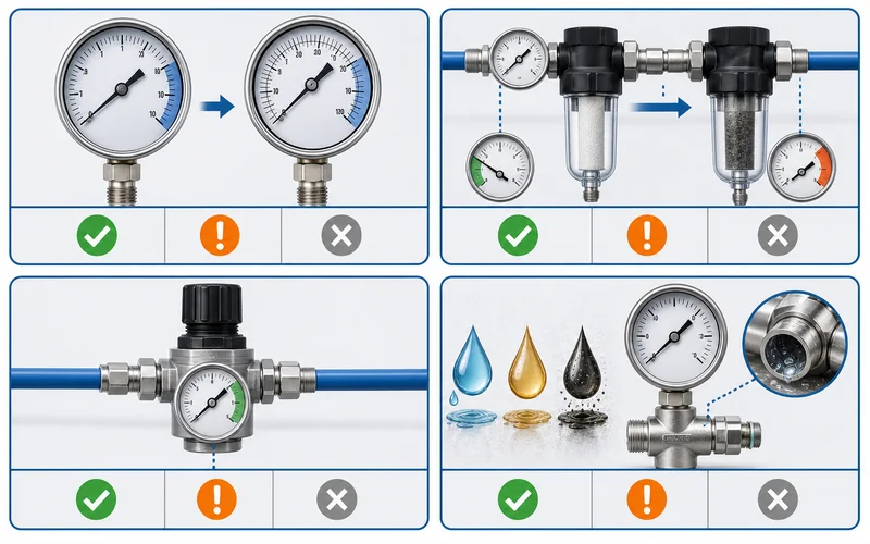
A pressure gauge does not measure flow, dew point, oil content, particle class, compressor efficiency or leak volume. Normal pressure at the receiver can exist while the farthest machine is starved during peak demand. Low pressure at a tool can come from a small hose even when the header is healthy. High pressure at the compressor can hide unnecessary energy use if regulators and leaks are compensating for poor distribution.
For high-risk or quality-critical pneumatic systems, pressure readings should be combined with flow meters, dew point monitoring, leak surveys, filter maintenance records and machine cycle data. Do not use catalog photos to infer certifications, oil-free cleanliness or safety approvals. Manogauge is a Zhejiang manufacturer with ISO 9001 quality management and export experience, but final compressed air pressure gauge selection must be confirmed against the plant standard and actual operating conditions.
RFQ checklist for compressed air pressure gauge selection
A useful RFQ should describe each measurement point instead of asking for a generic air gauge. Include normal pressure, maximum pressure, unit, compressor control band, dryer and filter model, regulator outlet set point, vibration level, pipe connection and viewing distance.
- State whether the gauge is for compressor discharge, receiver, dryer, filter, ring main, branch line or point-of-use regulator.
- Specify bar, psi, MPa or dual-scale dial requirements, and whether calibration documents are needed.
- Confirm dry or liquid-filled construction, dial diameter, accuracy class, case material, wetted material and window material.
- Define thread standard and mounting orientation: bottom, back, panel, valve manifold or regulator body.
- For filter pressure drop, decide whether two gauges, a differential pressure gauge or a transmitter is required.
With these details, compressed air pressure gauge selection becomes a maintenance decision based on pressure evidence, not a guess based on pipe size.
For system-level compressed air pressure monitoring — compressor-house instruments, dryer and filter differential pressure, and point-of-use pressure management — see the compressed air pressure monitoring guide.
Key takeaways
- One gauge cannot diagnose a low-pressure complaint: compressor control, receiver pressure, dryer and filter pressure drop, pipe size, leaks and regulator setting all produce the same symptom.
- Gauges before and after dryers and filters turn pressure drop into a maintenance signal, showing whether the drop is normal or rising.
- Choose the range so the normal reading sits near the middle of the dial; a gauge working near zero or near full scale is harder to read and shorter-lived.
- Pressure says nothing about flow, dew point, oil content or particle class — normal receiver pressure can coexist with a starved machine at the end of the line.
Related buyer pages
Liquid-filled pressure gauge supplierFilled gauges for compressor discharge, air receiver and pulsating air lines.
Stainless steel pressure gauge manufacturerStainless gauges for oil-free, instrument-air and washdown compressed-air points.
Digital pressure gauge supplierDigital gauges for leak surveys and specific-power auditing on air systems.
Related reading
- 316L vs Brass Pressure Gauge Wetted Parts: Corrosion Guide
316L vs brass pressure gauge wetted parts compared for corrosion risk in water, steam, ammonia, seawater, chlorides, CIP/SIP cleaning and diaphragm seals.
- A2L R-454B Refrigerant Pressure Gauge Selection
A2L R-454B refrigerant pressure gauge selection for HVAC service: manifold gauge use, PT chart checks, service ports, gauge range and safe workflow.
- Ammonia Refrigeration Pressure Gauge: R717 Materials and Safety
Ammonia refrigeration pressure gauge guide for R717 cold storage: suction, discharge, oil, defrost ranges, material compatibility and safety checks.
- Chemical Dosing Skid Pressure Gauge Selection Checklist
Dosing skid gauge selection: set range from pump shutoff and relief pressure, pick wetted materials and diaphragm seals, handle pulsation and clogging risk.
- Oxygen Pressure Gauge Selection Guide
Oxygen pressure gauge selection guide for clean service: oil-free handling, materials, range, dry case choice, packaging, installation and RFQ checks.
Frequently asked questions
Where should pressure gauges be installed in a compressed air system?
Use gauges at compressor discharge, receiver outlet, before and after dryers or filters, distribution headers and point-of-use regulators. The exact layout depends on the plant drawing and the maintenance question being answered.
What pressure range is best for a compressed air gauge?
Select range from normal pressure, maximum pressure and readability. The normal value should be easy to read, commonly near the middle of the dial, while receiver and compressor points still need suitable overpressure margin.
Can a pressure gauge find compressed air leaks?
A gauge can show pressure loss under demand, but it cannot measure leak volume or locate the leak. Use leak surveys, flow data and ultrasonic detection for leak confirmation.
Do filters need a differential pressure gauge?
For maintenance decisions, compare pressure before and after the same filter. This can be done with two gauges, a differential gauge or a transmitter, depending on whether local reading, alarm or trend data is required.
Should compressed air gauges be brass or stainless steel?
Match wetted material to condensate, oil carryover, plant standards and corrosion exposure. Stainless steel is often conservative for wet, outdoor or washdown areas, but the final choice should be confirmed for the actual air quality.
How much pressure drop is acceptable in a compressed air system?
There is no standard limit, so it is set by design. A common budget allows roughly 0.1-0.2 bar across the aftercooler, 0.2-0.3 bar across the dryer, about 0.1 bar across each clean filter, and under 0.2 bar across the distribution main, with the hose and coupling at the tool often the largest single loss. ISO 8573-1 classifies air purity, not pressure drop, so the numbers have to come from the equipment data sheets and the plant's energy target.