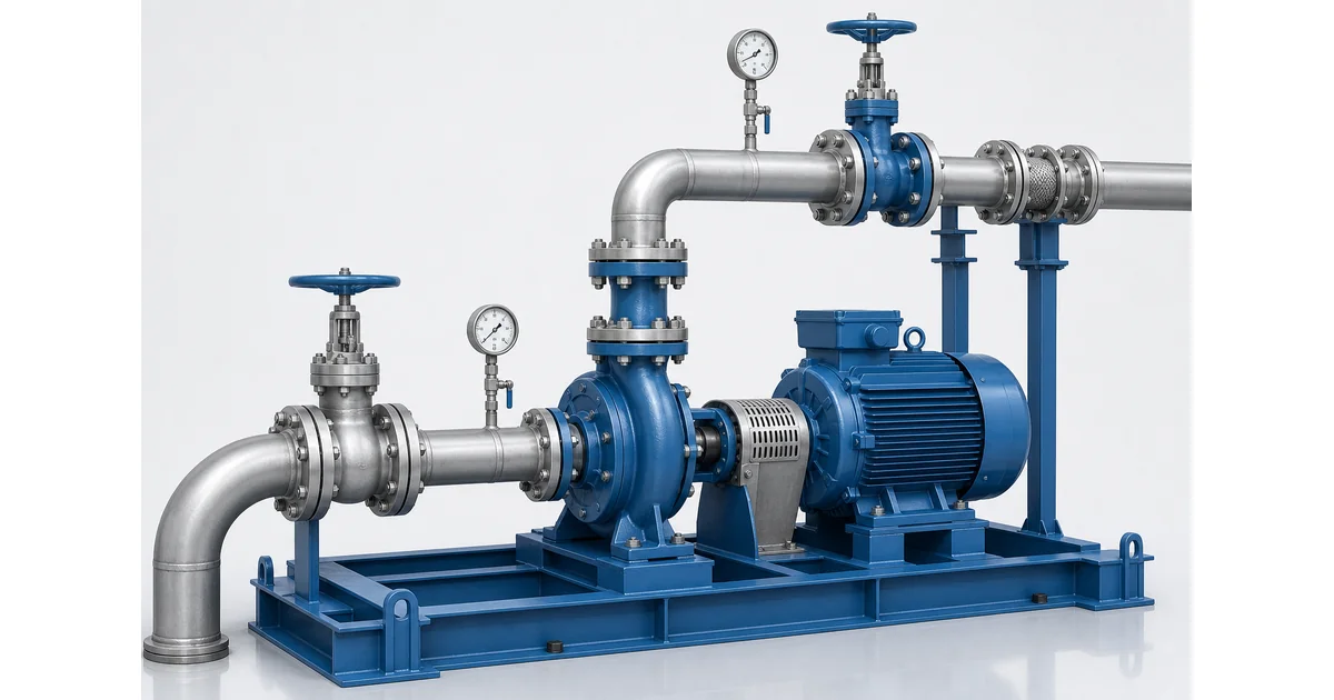
Centrifugal pump pressure gauge selection starts with a simple question: what decision should the reading support? A suction gauge, a discharge gauge and, in some systems, a differential pressure point can turn a pump skid into a practical diagnostic station. The readings still need pump curve, flow and fluid context, but they give maintenance teams a fast way to notice restriction, vibration, cavitation risk and operating-point changes.
Why centrifugal pump pressure gauge selection matters
Centrifugal pump pressure gauge selection is the process of choosing the right gauge type, range, accuracy, connection and protection for pump suction and discharge service. A pump gauge is not only a pressure indicator. When suction and discharge readings are taken at sensible points, they help operators estimate differential pressure, compare the pump against its curve, find clogged strainers, detect valve changes and decide whether a low-flow problem is hydraulic or mechanical.
The U.S. Department of Energy notes that pump systems can achieve major energy and cost savings through good energy management and efficient equipment choices; field pressure data is one of the practical signals used during a pump-system survey. See the DOE Pump Systems resource for broader system-efficiency context. For related instrument basics, review the pressure gauge accuracy class selection guide and the pressure gauge snubber selection guide.
Check Pressure Gauge Range OptionsExplore 143+ industrial gauge models→Place gauges where suction and discharge readings support decisions
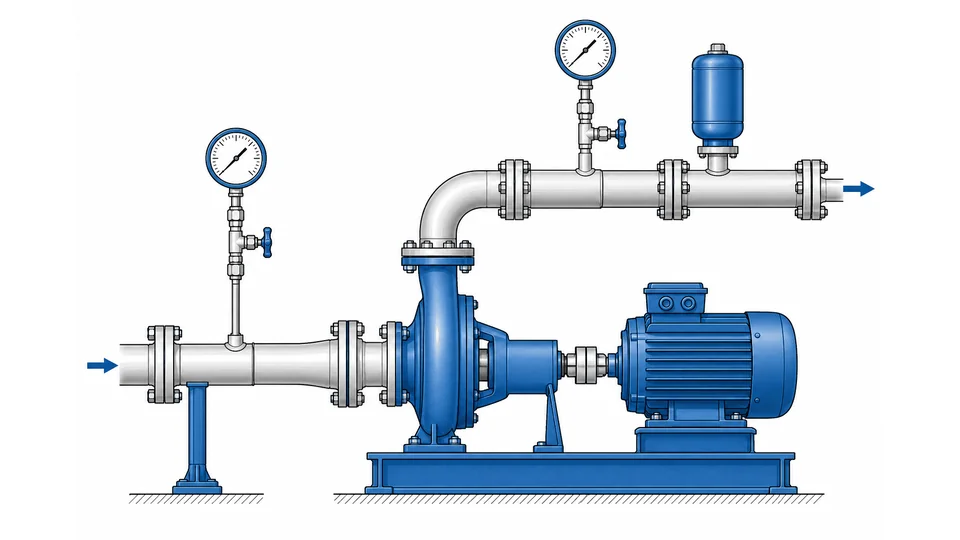
For most centrifugal pumps, a gauge near the suction nozzle and a gauge near the discharge nozzle provide more value than a single downstream gauge. The suction reading helps expose inlet restriction, low tank level, blocked strainers and possible cavitation risk. The discharge reading shows the pressure the system is demanding at the current flow condition. Together, they form the pressure difference that can be converted to head for comparison with the pump curve.
| Measurement point | What it can indicate | Common instrument choice |
|---|---|---|
| Suction line before pump inlet | Low inlet pressure, strainer loading, tank-level change, NPSH concern | Compound gauge or transmitter with vacuum range if suction can drop below atmosphere |
| Discharge line near pump outlet | System resistance, closed valve, worn impeller, operating-point change | Bourdon tube gauge, liquid-filled gauge, or transmitter |
| Across filter or strainer | Loading and cleaning interval | Differential pressure gauge or two local gauges |
Read the pair, not the gauges: converting suction and discharge into pump head
Two gauges on a pump only become useful when the pair is read together. The difference between discharge and suction pressure is what the pump is actually producing, and it is the number that can be compared against the manufacturer's pump curve. For a cold, water-like liquid, differential head in metres is approximately the differential pressure in bar multiplied by 10.2 and divided by the specific gravity of the pumped fluid. A pump reading 6.2 bar at discharge and 0.4 bar at suction is producing 5.8 bar differential, which is roughly 59 m of head on water and about 68 m on a fluid with a specific gravity of 0.87.
That conversion is the reason suction and discharge gauges should share the same pressure unit, a comparable accuracy class and, where the layout allows, the same elevation. Pairing a 0-10 bar class 2.5 discharge gauge with a -1/+1.5 bar class 1.6 suction gauge is workable, but the combined uncertainty has to be understood before anyone declares a pump degraded. A class 2.5 gauge on a 0-10 bar dial may deviate by 0.25 bar on its own, and 0.25 bar is already about 2.5 m of apparent head on water.
| What the operator reports | Typical gauge signature | What to check before blaming the pump |
|---|---|---|
| Noise, vibration, unstable delivery | Suction reading lower than expected, pointer fluttering | Strainer condition, suction valve position, level and temperature in the source vessel, available NPSH |
| Delivery falls off over months | Both readings steady, differential short of the duty point on the curve | Wear ring clearance, impeller condition, actual shaft speed, entrained gas |
| Discharge pressure high, little or no flow | Discharge sitting near the shutoff head of the curve | Throttled or closed discharge valve, blocked line, wrong impeller diameter |
| Complaint persists, readings look normal | Differential matches the curve at the stated speed | Instrument error, downstream restriction, or a flow problem no pressure gauge can see |
Pump standards such as API 610 (ISO 13709) for petroleum service and ISO 5199 for chemical process pumps set the mechanical and testing framework for the pump itself. They do not select the local gauge. What they do imply is that a gauge used for performance verification has to be repeatable enough to show a trend, and installed where the reading is not corrupted by turbulence from an elbow or a partly open valve.
Record the commissioning values. A pair of readings taken at a known flow, speed and liquid temperature on the day the pump was accepted is the reference against which every later reading is judged, and it takes five minutes to capture. Without that baseline a differential pressure reading is only a number. The pressure gauge failure modes guide covers the instrument-side causes of a drifting reading, and accuracy class selection explains how much of an apparent change is simply permitted error.
Choose the pressure range from normal, start-up and upset conditions
The selected range should keep normal operating pressure in the most readable part of the dial while still surviving start-up and upset conditions. As a rule of thumb, many mechanical gauges last longer when steady operating pressure sits around 25-75% of full scale and pulsating service stays lower in the span. The final range must follow the pump package data, system design pressure and site safety rules.
Do not size the discharge gauge only from pump nameplate pressure. Review shut-off head, relief-valve setting, hydrostatic test pressure, fluid specific gravity and whether the pump may run against a closed valve. On suction service, specify a compound or vacuum-capable gauge when the line can operate below atmospheric pressure.
The arithmetic behind these percentages, the standard range series and three worked examples are set out in how to calculate pressure gauge range.
Prepare a Pump Gauge RFQ ChecklistOur engineers respond within 24 hours→Dry, liquid-filled, stainless steel or transmitter: selecting the instrument type
A dry Bourdon tube gauge is suitable for clean, steady water or utility service where vibration is low and operators need a simple local reading. A liquid-filled gauge is usually better on pumps with vibration, rapid valve movement or pressure pulsation because the fill damps pointer flutter and movement wear. Stainless steel wetted parts are preferred for corrosive liquids, outdoor pump skids, washdown rooms and many chemical services. A pressure transmitter is better when the control room needs alarms, trends or pump performance data.
For dirty, viscous or crystallising liquids, a diaphragm seal may be required so the process cannot block the Bourdon tube. For severe pulsation, combine a liquid-filled gauge with a snubber or restrictor only after checking response time and clogging risk.
Installation details that make pump gauge readings reliable

Good pump readings depend on good installation. Mount gauges where they are visible, supported and isolated from direct pipe strain. Use an isolation valve so the gauge can be removed for calibration. Add a bleed or vent point where trapped gas or liquid can distort the reading. Keep impulse lines short, protect the gauge from pump vibration, and avoid dead legs that trap solids or stagnant liquid.
- Confirm suction and discharge tapping locations against the pump and piping drawing.
- Match NPT, BSP, G or metric threads before installation; do not force unlike thread forms.
- Use a snubber or liquid fill when pointer flutter is present.
- Record readings at the same pump speed and valve position during baseline checks.
Risk boundaries: what pump pressure gauges cannot prove
A pump pressure gauge does not prove flow rate by itself. It cannot confirm NPSH margin without vapor pressure, elevation, velocity and friction-loss data, and it cannot identify every internal pump fault without a pump curve, flow reading, vibration data and maintenance history. A normal discharge pressure can still hide low flow if a valve is throttled; a low discharge pressure can come from an open bypass, wrong rotation, worn impeller or a faulty gauge.
Use pressure gauges as part of a wider diagnostic set. For high pressure, hot liquid, hazardous chemical, food-grade, pharmaceutical or explosion-risk service, confirm material compatibility, overpressure protection, cleanliness requirements, temperature limits, standards and installation practices with the pump OEM and site engineer before ordering. Manogauge can support gauge selection from Zhejiang manufacturing resources, but final suitability belongs to the project specification.
Centrifugal pump pressure gauge selection checklist
Before ordering, collect the normal suction pressure, normal discharge pressure, maximum upset pressure, fluid name, temperature, viscosity, specific gravity, pulsation level, vibration level, installation thread, dial size, accuracy class, case material and wetted material. A clear RFQ avoids under-ranged gauges, wrong threads and instruments that fail early in vibration or corrosive service.
In short, centrifugal pump pressure gauge selection works best when suction and discharge readings are treated as system diagnostics, not as isolated numbers on a dial.
For pump discharge and suction gauges with glycerin or silicone fill for vibration and pulsation damping, see Manogauge's liquid filled pressure gauge supplier page.
Key takeaways
- A suction gauge and a discharge gauge together turn a pump skid into a diagnostic station; a single downstream gauge cannot separate inlet restriction from system demand.
- Mechanical gauges last longer when steady operating pressure sits around 25-75% of full scale, and pulsating service should sit lower in the span.
- Liquid-filled gauges suit pumps with vibration, rapid valve movement or pulsation, because the fill damps pointer flutter and reduces movement wear.
- A pump gauge cannot prove flow rate or confirm NPSH margin on its own — that needs vapour pressure, elevation, velocity and friction-loss data plus the pump curve.
Related buyer pages
Liquid-filled pressure gauge supplierSuction and discharge gauges that survive cavitation, pulsation and base-plate vibration.
Stainless steel pressure gauge manufacturerStainless wetted parts for chemical, seawater and water-treatment pump duties.
Related reading
- Industrial Heat Pump Pressure Monitoring Guide
Industrial heat pump pressure monitoring for retrofits: gauge and transmitter selection, range, materials, installation points and commissioning checks.
- 316L vs Brass Pressure Gauge Wetted Parts: Corrosion Guide
316L vs brass pressure gauge wetted parts compared for corrosion risk in water, steam, ammonia, seawater, chlorides, CIP/SIP cleaning and diaphragm seals.
- A2L R-454B Refrigerant Pressure Gauge Selection
A2L R-454B refrigerant pressure gauge selection for HVAC service: manifold gauge use, PT chart checks, service ports, gauge range and safe workflow.
- Hydraulic Pressure Gauge Selection Guide
Hydraulic pressure gauge selection for presses, power units and manifolds: 0-600 bar ranges, glycerine fill vs snubbers, SAE/BSP/NPT ports and fluid checks.
- Pressure Gauge Supplier Audit Checklist
Pressure gauge supplier audit checklist: ISO 9001 scope, EN 837 and ASME B40.100 compliance, calibration traceability, sample testing and material certs.
Frequently asked questions
Do centrifugal pumps need gauges on both suction and discharge?
For diagnostics, yes. The suction reading shows inlet restriction and cavitation risk signals, while discharge pressure shows system resistance. Together they support differential pressure and head checks.
What range should a pump discharge pressure gauge use?
Choose a range that keeps normal pressure in the readable middle portion of the dial while surviving shut-off head, relief settings and upset pressure. Confirm against the pump package and site design pressure.
Should pump gauges be liquid-filled?
Use liquid-filled gauges where vibration or pulsation causes pointer flutter. For clean steady service a dry gauge may be enough; severe pulsation may also need a snubber or transmitter strategy.
Can pressure gauges prove pump flow?
No. Pressure readings help infer operating condition, but flow confirmation needs a flow meter, pump curve, speed, fluid properties and system data.
When is a transmitter better than a local gauge?
Use a transmitter when alarms, trend history, remote monitoring or control-room data are required. Many pump skids still keep a local gauge for maintenance and commissioning.
How should the suction-side pressure gauge range be sized for a centrifugal pump?
Suction pressure gauges must read the full suction pressure range including worst-case low-pressure conditions, while maintaining legibility. For pumps with flooded suction at 0–2 bar gauge, a 0–4 bar range is appropriate. For pumps with suction lift or vacuum on the suction side, specify a compound gauge reading vacuum and pressure. The suction gauge is critical for NPSH (Net Positive Suction Head) monitoring — undersized or misranged gauges mask cavitation risk.
How often should centrifugal pump pressure gauges be replaced or recalibrated?
Gauges on high-vibration pump installations (direct-mounting without syphon or isolation) typically require replacement every 1–2 years due to vibration fatigue. Liquid-filled gauges on pump bodies or dampened via flexible tubing can last 3–5 years. Include pump gauges in the plant preventive maintenance schedule and inspect for pointer drift, fogged window, or fill-fluid discoloration annually. Replace any gauge where zero error exceeds the accuracy class tolerance.
How do I convert pump suction and discharge gauge readings into head?
Subtract suction pressure from discharge pressure to get the differential, then multiply the differential in bar by 10.2 and divide by the specific gravity of the liquid to get head in metres. A differential of 5.8 bar on water is about 59 m; on a liquid of specific gravity 0.87 the same 5.8 bar is about 68 m. Compare that figure with the pump curve at the actual shaft speed, not the nameplate speed.
Why should suction and discharge gauges have the same accuracy class?
Because the useful number is the difference between them, and the two errors add. A class 2.5 gauge on a 0-10 bar dial is permitted to deviate by 0.25 bar, which is roughly 2.5 m of head on water. If the suction gauge is class 1.6 and the discharge gauge is class 2.5, the differential carries the sum of both permitted errors, so a small genuine loss of performance can hide inside the instrument tolerance.