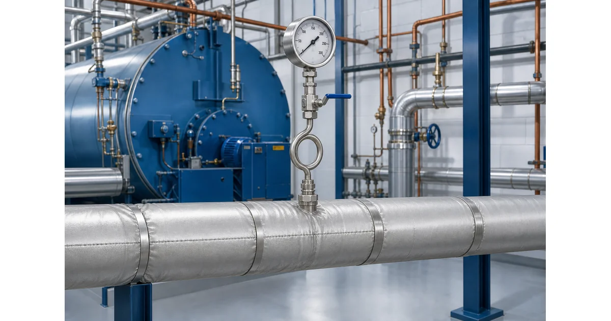
A steam pressure gauge siphon is a looped or bent tube installed between a steam pressure tapping and the gauge. It retains condensate so pressure reaches the sensing element while direct hot steam does not. Correct selection depends on orientation, pressure and temperature rating, material, thread, valve arrangement, ambient conditions and the gauge itself.
What a steam pressure gauge siphon does and does not do
A steam pressure gauge siphon is a thermal protection accessory. Steam entering the loop condenses and the retained water column transmits static pressure to the Bourdon tube. WIKA describes this condensate barrier and recommends filling a new siphon with water or another suitable separating liquid before commissioning in its pressure gauge siphon technical description.
The siphon does not reduce the steady process pressure at the gauge. It is not a relief valve, pressure regulator, check valve or proof that the boiler is operating safely. It also does not correct an unsuitable range, damaged movement, blocked pressure tapping or missing calibration. Treat the assembly as one measurement chain: process tapping, siphon, isolation valve, connection, gauge and safe access.
For related fundamentals, review pressure gauge installation best practices and the industrial pressure gauge selection guide.
Review Pressure Gauge Specification Options →Explore 143+ industrial gauge models→How the condensate barrier protects a boiler pressure gauge
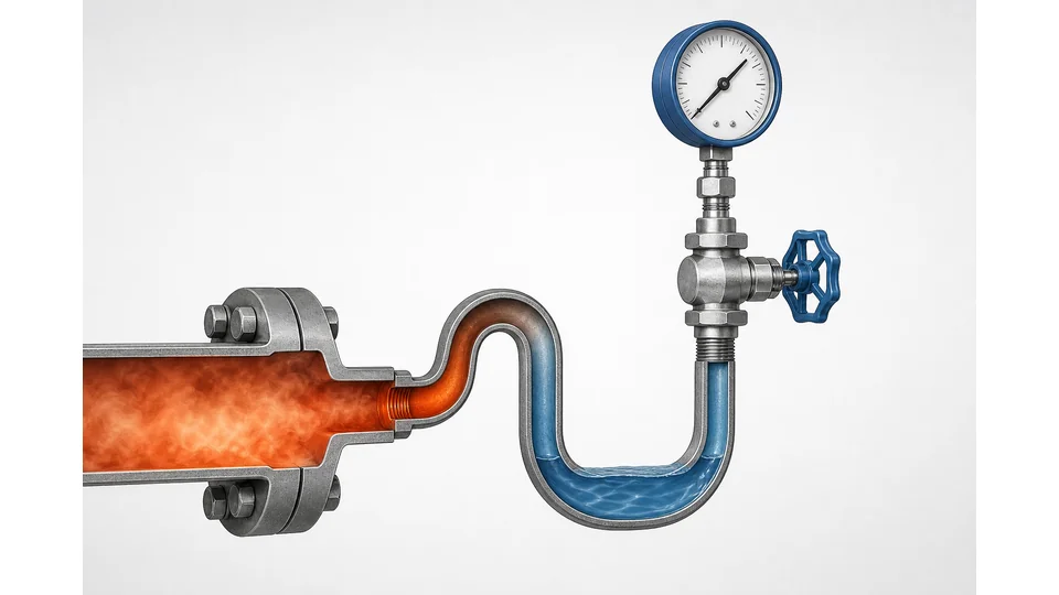
When steam first enters a cool siphon, part of it condenses. The liquid collects in the low section and becomes the pressure-transmitting barrier. Heat is lost through the siphon wall and surrounding air, so the fluid reaching the gauge is cooler than the steam main. The actual cooling depends on geometry, material, ambient temperature, airflow, insulation and whether the condensate remains in place.
The barrier must exist from startup. Prime the siphon before exposing the gauge to live steam, following the approved site procedure. Do not assume a dry loop will immediately protect the instrument. Check frost exposure as well: trapped water can freeze, expand and damage the siphon or gauge. Outdoor arrangements may require a site-engineered freeze-protection method that does not defeat heat dissipation.
Insulating the entire siphon can reduce its ability to cool the process medium. Any insulation, heat tracing or enclosure around the instrument take-off should therefore be reviewed against the gauge temperature limit and plant freeze strategy.
Pigtail, coil and U-form siphon selection by orientation
Geometry must suit the pressure tapping. Product naming varies by supplier, so purchase drawings matter more than informal names. WIKA identifies pigtail arrangements for vertical installations and coil arrangements for horizontal installations; other suppliers use ring, U-form or trumpet-form terminology.
| Installation condition | Typical arrangement | Selection check |
|---|---|---|
| Top or vertical pressure tapping | Pigtail, ring or trumpet form | Loop can retain liquid and gauge remains upright |
| Horizontal pressure tapping | Coil or U-form | Drawing matches flow path, headroom and support |
| High vibration or limited clearance | Compact thermal barrier or remote arrangement | Supplier rating, support and heat rejection are confirmed |
| Outdoor freezing risk | Site-specific engineered layout | Drainage, freeze protection and safe restart procedure are defined |
Confirm maximum allowable pressure and temperature, schedule or wall thickness, material, process and instrument threads, thread gender, corrosion allowance and any required cleaning. Never infer a pressure rating from tube appearance alone.
Request a Steam Gauge Assembly CheckOur engineers respond within 24 hours→Selecting the boiler pressure gauge, range, material and valve
The boiler pressure gauge must be specified separately from the siphon. Define normal operating pressure, startup and upset pressure, required scale unit, dial size, accuracy class, connection, case construction and ambient temperature. Spirax Sarco's gauge, siphon and cock installation instructions recommend protecting gauges on steam or hot gas with a siphon and priming the siphon before fitting the gauge.
Choose wetted material for the condensate chemistry and external atmosphere. Carbon steel, brass and stainless steel options have different limits; do not assume stainless steel is automatically suitable for every chloride, chemical-treatment or high-temperature condition. Match NPT, BSP, G or other threads exactly and use the specified sealing method.
An isolation valve or gauge cock supports removal and calibration, but its pressure-temperature rating and operating procedure must match the installation. The valve must not create an unsafe trapped-pressure condition during maintenance. The industrial pressure gauge catalog can identify candidate gauge families; final range, material and documentation require confirmation against the boiler and site requirements.
Steam gauge installation and commissioning checklist
Before installation, isolate, depressurize and cool the pressure connection under the site's approved safety procedure. Verify that the tapping is open and clean, but never probe or loosen a live steam connection. Support the assembly so the siphon and gauge do not impose damaging leverage on a small branch connection.
- Confirm the approved drawing, pressure-temperature rating, material and thread at every joint.
- Install the siphon in the orientation specified by its manufacturer.
- Prime it with the approved separating liquid before admitting steam.
- Install the isolation valve in an accessible position with a defined operating state.
- Tighten the gauge using the connection flats, not by twisting the case.
- Admit pressure gradually and inspect from a safe position for leakage, abnormal vibration and temperature.
- Compare the reading with an independent reference or expected operating condition and record the commissioning result.
After maintenance, test any associated alarms or protective functions. A local indicating gauge should not be treated as the sole protective device for a boiler.
Fault symptoms, maintenance and engineering boundaries
A gauge that becomes unusually hot may indicate a lost condensate barrier, an incorrect siphon orientation, insulation around the cooling section or excessive process conditions. Slow response can come from a blocked tapping, contaminated valve, viscous deposits or a partially obstructed siphon. Pointer oscillation may indicate pulsation or vibration; do not assume the siphon alone will provide sufficient damping.
- Reading stays at zero: verify isolation-valve position, blockage and instrument condition under a safe isolation.
- Reading differs from a reference: check range, calibration, trapped gas or liquid head, temperature exposure and reference accuracy.
- Leaks or corrosion: remove the assembly from service and verify material, thread engagement and pressure rating.
- Freeze event: inspect the entire liquid-filled path before restart; hidden deformation can invalidate the assembly.
A steam pressure gauge siphon cannot establish relief-valve capacity, allowable boiler pressure, code compliance or safe operating limits. Those decisions require the boiler documentation, applicable jurisdictional rules and qualified engineering review. Use this guide as a specification and inspection checklist, not as authorization to modify a live steam system.
Key takeaways
- A siphon protects against direct steam temperature by retaining a condensate barrier; it does not reduce steady pressure.
- Geometry, orientation, pressure-temperature rating, material and thread must be confirmed as one assembly.
- Prime before steam service, check freeze risk and keep boiler safety decisions separate from the local gauge.
Related products
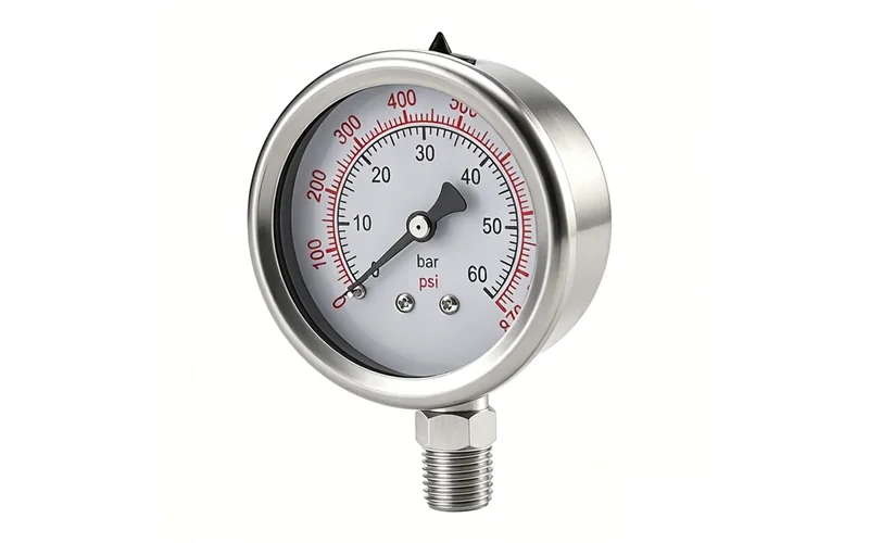
- Liquid-Filled Pressure Gauge - Radial (ZX-06-R) — 0–60 MPa
- Shock-Resistant Pressure Gauge - Radial (ZX-03-R) — 0–270 psi
Frequently asked questions
Does a steam pressure gauge siphon reduce pressure?
No. In steady service the condensate transmits essentially the same static pressure to the gauge. The siphon's primary purpose is thermal separation, not pressure regulation.
Should a pressure gauge siphon be filled before startup?
Yes. Manufacturer instructions commonly recommend priming it with water or another suitable separating liquid before admitting steam, using the site's approved procedure.
Which siphon shape is used for vertical and horizontal tapping?
Pigtail or ring arrangements are commonly used for vertical tapping, while coil or U-form arrangements are commonly used for horizontal tapping. Confirm the supplier drawing.
Can a steam siphon freeze?
Yes. Retained water can freeze and damage the siphon or gauge. Outdoor layouts require a reviewed freeze-protection, drainage and restart strategy.
Is a siphon enough to make a boiler pressure gauge safe?
No. Gauge range, material, valve, pressure-temperature ratings, calibration, relief protection, boiler documentation and local rules all require separate confirmation.